
Electrical diagrams are essential for the development of electrical projects, ensuring proper organization and system functionality. They serve as a visual representation of circuit connections and components, making them indispensable for engineers, technicians, and electricians. With technological advancements, specialized software like E3.series offers tools that optimize the creation, editing, and documentation of these diagrams, ensuring greater accuracy and efficiency. In this article, we explore the key aspects of electrical diagrams and how E3.series can transform this process.

See the full article and optimize your processes!
Contents of this Article
- What is an Electrical Diagram and Its Importance
- Types of Electrical Diagrams
- Automation and Error Reduction with E3.series
- Visualization and Simulation for Better Understanding
- Compliance with Standards and Comprehensive Documentation
- Conclusion
- Teste E3.series
1. What is an Electrical Diagram and Its Importance
An electrical diagram is a graphical representation of an electrical circuit, displaying connections, devices, and current flow in a clear and organized manner. These diagrams are crucial for designers, manufacturers, and technicians as they serve as a reference for assembly, maintenance, and fault diagnosis. The use of digital tools like E3.series allows for the creation of more precise diagrams, reducing manual errors and ensuring compliance with technical standards.
Try NOW the industry-leading E-CAE E3.series tool in the world with technical training courses!
Click on the banner below
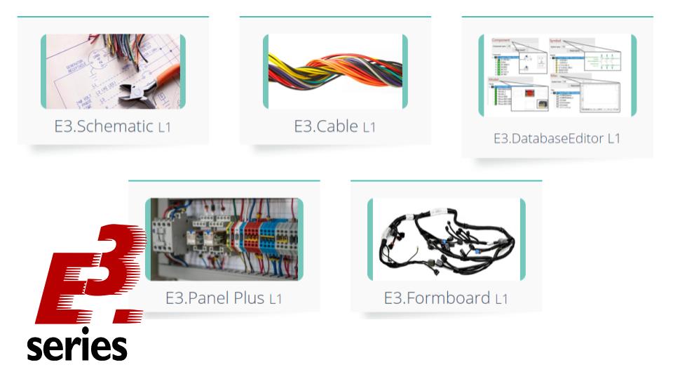
2. Types of Electrical Diagrams
There are different types of electrical diagrams, each serving a specific function within a project. Schematic diagrams, for example, detail the interconnection of electrical components, while wiring diagrams physically represent how wires and cables are connected. Layout diagrams, on the other hand, help organize components within electrical panels. E3.series supports all these types of diagrams, allowing for the creation of comprehensive and integrated projects.
3. Automation and Error Reduction with E3.series
Creating electrical diagrams manually can be a time-consuming and error-prone process. With E3.series, various development stages can be automated, such as wire numbering, bill of materials generation, and connection verification. The software also enables the reuse of standardized projects, reducing rework and ensuring greater consistency in electrical designs.
4. Visualization and Simulation for Better Understanding
While E3.series does not perform functional simulations, it allows for detailed 2D and 3D visualization of diagrams, facilitating the identification of potential interferences and design optimizations. This feature enables engineers and designers to analyze project feasibility before manufacturing, ensuring greater efficiency and reducing rework costs.
5. Compliance with Standards and Comprehensive Documentation
Compliance with technical standards is a crucial factor in creating electrical diagrams. E3.series adheres to international standards such as IEC and ANSI, ensuring that projects meet market requirements. Additionally, the software automatically generates detailed documentation, facilitating audits, approvals, and communication among technical teams.
Conclusion
Electrical diagrams are fundamental for the development of efficient and safe projects. Using specialized software like E3.series not only enables the creation of precise diagrams but also automates processes, reduces errors, and ensures compliance with technical standards.

For companies and professionals looking to optimize workflow and improve the quality of electrical projects, E3.series presents itself as a comprehensive and innovative solution.
Do the E3.series Trial according to your demand using the button below!

Are You a Student?
Download E3.series for free!