In this article you can check how to document your electrical schematics with the generation of terminal plan. E3.series allows the intelligent generation of these spreadsheets instantly. The information they contain is directly linked to the rest of the project and is automatically updated. See the full video article and optimize your processes!
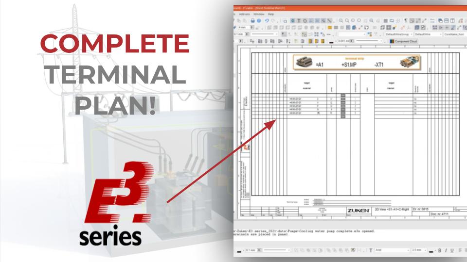
How to Generate the Terminal Plan
With a previously opened project, the terminal sheet is generated through the option "Insert" - "Terminal Plan". In the window for defining the configurations, it is possible to choose the type of table organization, name, sheet type, external and internal definitions, among other options presented in the figure below.
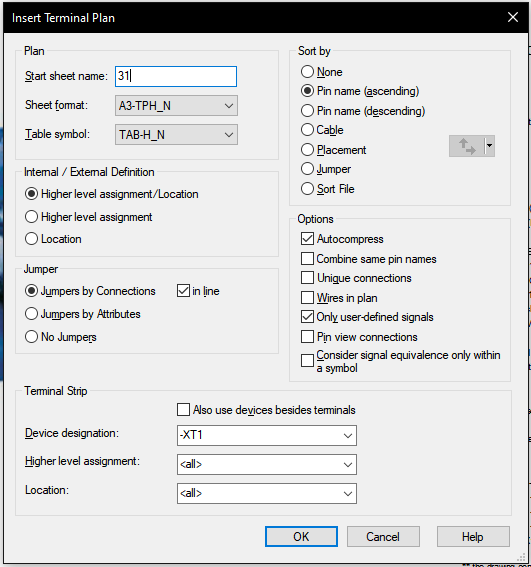
Settings for Inserting the Terminal Plan
In this example, the definitions were as follows:
- Sheet Name: "31";
- Sheet Format: "A3-TPH_N";
- Table Symbol: "TAB-H_N";
- Ascending Pin Order;
- Device Designation: "-XT1".
Try NOW the industry-leading E-CAE E3.series tool in the world with technical training courses!
Click on the banner below
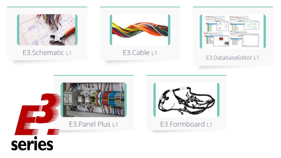
Table Properties
Also, it is possible to rearrange the location of the sheet in the project folders. To do this, right-click on the sheet and click on "Sheet Properties". Then, in the "Document Type" field, select where you would like to position the sheet.
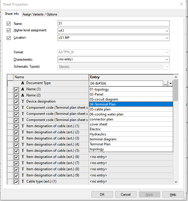
Definition of Sheet Properties
In this example, the option "04-Terminal Plan" was selected.
Watch the Full Video
Subscribe to our Youtube channel here for more technical videos.
Interconnected Information
The information contained in the table is linked to the rest of the project and we can jump to the schematic and visualize the items.
The Information is Interlinked with the Rest of the Project.
Just right click on the desired item and select "Jump" - "Jump to Schematic".
Make the E3.series Trial according to your demand using the button below!

Are You Student?
Download E3.series for free!