In this article we show how the creation and editing of an electrical panel can be performed in E3.series software. Creation is simple and in a few steps a new electrical panel is created. With the functionality and intelligent settings of auto-routing connections are made with one click. See the full video article!
.jpg?width=960&name=HowtoCreateElectricPanels%20(2).jpg)
First Steps for Panel Creation
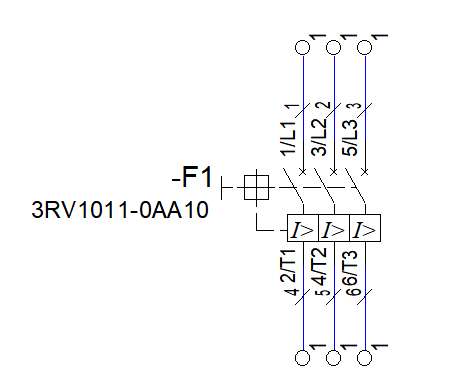
Creation begins with placing the dashboard items on the schematic sheet. Terminal and breaker components are easily dragged from the database to the project sheet.

Then the connections and wires are inserted. The wire parameters must respect the circuit breaker limits, otherwise the E3.series will intelligently not allow the addition of these wires.
Interconnected Projects between E3.schematic and E3.panel
After working on the schematic sheet, a new panel-type sheet is inserted for the assembly of the electrical panel, with the plates, ducts and channels for the terminals and circuit breakers.
Connections between terminals and circuit breaker are automatically referenced because the designs and sheets between E3.schematic and E3.panel work together.

Try NOW the industry-leading E-CAE E3.series tool in the world with technical training courses!
Click on the banner below
Automatic Routing and Parameters for Directions
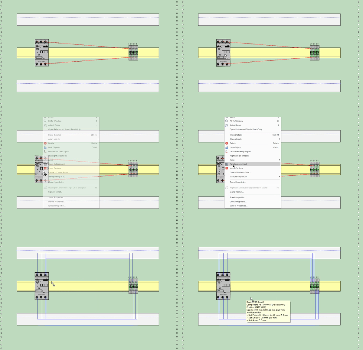
Device routing is done with a single click. With the right mouse button the option "Panel Autoconnect" connections are performed automatically and instantly.

In addition, E3.series allows the configuration of attributes to inform where each terminal should be routed, through the upper part of the channel or the lower part.
Watch the Full Video
Subscribe to our Youtube channel here for more technical videos.
Graphical Features
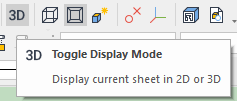
- "Toggle Display Mode"

- "Display Step Models in 3D"

- "Graphics from 2D in 3D".

Make the E3.series Trial according to your demand using the button below!
Are you a student?
Download E3.series here for free!


