In this week's tech tip, the creation of a single-line view of a component is presented. A new symbol is created in the database and its text attributes are inserted. Afterwards, a new component, three-line symbol and model are added and the pins are automatically related. At the end, the initially created symbol is added as a single-line view.
E3.series Electrical Projects - Creation of Single-Line Component View
Posted by Arthur Hoerlle Jul 22, 2021
In this article, you will learn some basic concepts about E3.series database such as: Attributes, Attribute Lists, Text Types, Connection Types, Braided Wire Parameters, among others. Besides, the creation of a component will be exemplified and how you can fully learn all the functionalities of the E3.series Database with DOWNLOAD of the tool and Courses.
In this video, E3.series' automatic routing functionality is presented by defining filters. Creating filters is useful because it allows routing to be performed by the desired side and channels. For example, parts of the project that are to be routed from the left can thus be defined with an order within the device property and the routing is done automatically.
There are numerous challenges faced by harness design and manufacturing teams across all industries. In some, weight is the biggest challenge and in others, signal reliability is paramount. The discussion today is less about using a harness and more about essential information to ensure your design and manufacturing processes work efficiently. Best practices that help significantly reduce the cost and time associated with harness fabrication are applicable from the earliest design stages and continue to be profitable throughout the process.
Creating symbols in E3.series is fast and intuitive. The symbol is graphically created in a project and exported as DXF/DWG for import into the database editor. Pins are added and device designation and master reference texts can be added.
As a way of thanking the 15,000 students on our courses at Udemy. Cim-Team organizes the E3.fundamentals course. See all the details in this article:
In this article we show how the insertion of wires inside E3.series is smart and complete. Thus, your projects are documented in detail so that your process becomes optimized and efficient.
Learn more about the study version of E3.series, E3.Student and see how to download it for students and those interested in solutions for electrical projects.
In this article, we show how the beginning of creating a panel can be simple and fast inside E3.series.
E3.Schematic - The Electrical Diagram Project Made Quickly and Intelligently

Posted by Andrei Seben Fontana Jun 08, 2021
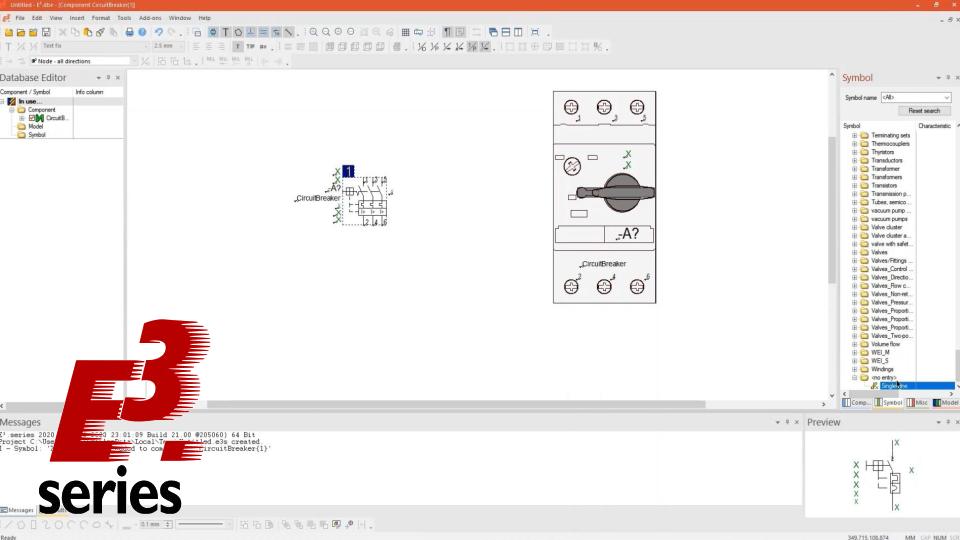
E3.schematic is considered the base module of the E3.series electrical engineering software. It provides an easy-to-use solution for creating and documenting electrical control systems, including schematics, terminal strips and PLCs. Its object-oriented architecture ensures an integrated and consistent design approach, helping to eliminate errors, improve quality and reduce design time. It is, without a doubt, the most used and disseminated tool among the most diverse operations of electrical engineering and automation projects in the world, serving as an initial step towards more complex solutions and additions to industrial processes.
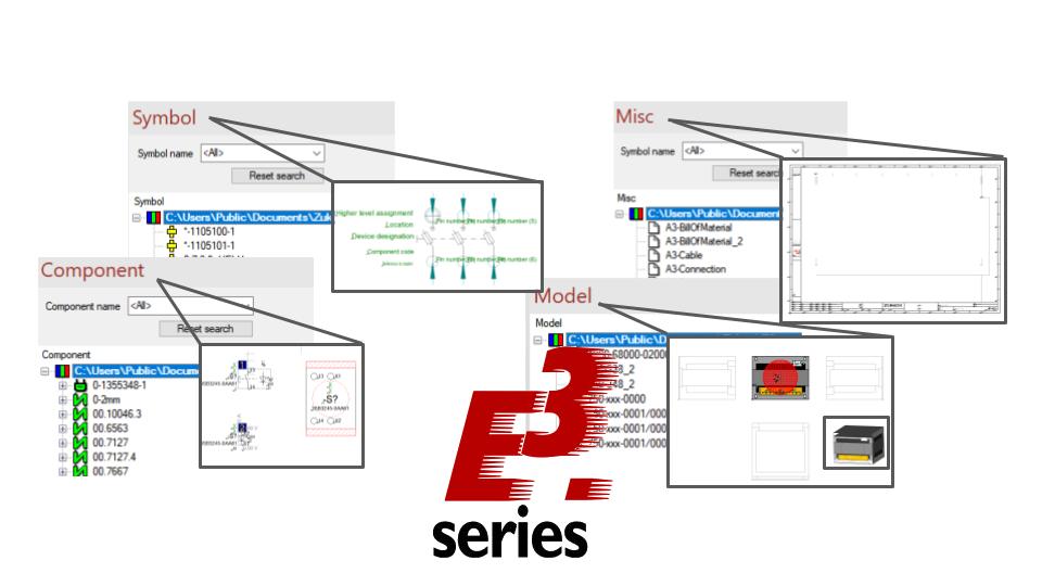
Among its key features is real-time design rule checking (DRCs) used to identify and prevent errors during the design phase of the project. In addition, it has a comprehensive library of components from suppliers such as ABB, Siemens, Schneider and Bosch which assists in the realization of projects with an automatic selection of components. See these and other main features of E3.schematic below.