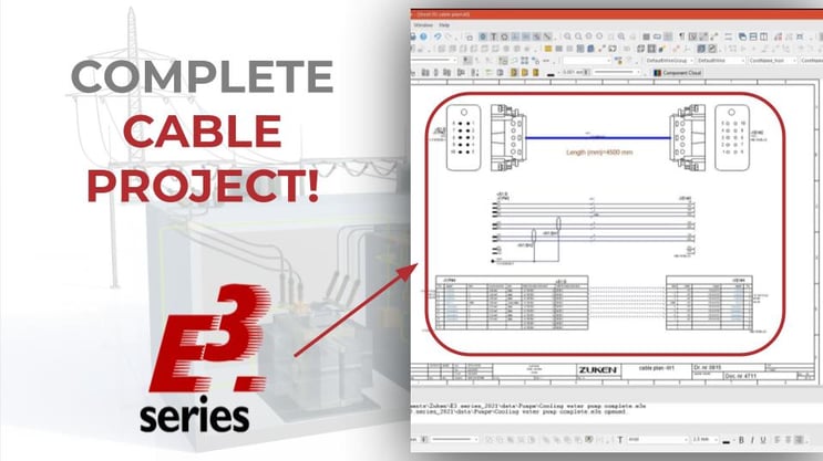
In this article, you can check how cable design and design works in E3.series software. The E3.cable module allows documentation and complete design of cables and harnesses with intelligent functionalities, so that your work is as optimized and efficient as possible. See the full video article and optimize your processes! See the full video article and optimize your processes!
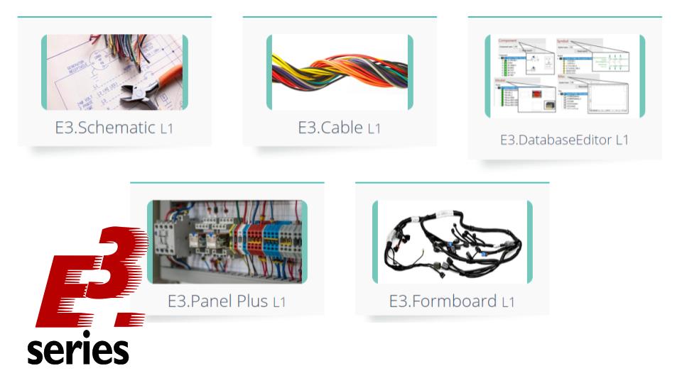
The E3.cable
It's the module made for creating detailed electrical diagrams, complex cables and harnesses, as well as allowing multiple views of the same device. It also encompasses the set of features of the E3.Schematic module. With it you can create, connect block diagrams and document your complete system.
Complete Documentation with E3.cable
Recommended for the demands of:
- Machinery and plant applications
- Supply system suppliers for the automotive, aviation and heavy vehicle industries.
Some of its main features are:
- Draw with Multiple Views
- Block diagram
- Hierarchical Blocks
- Automatic connector selection
- Automatic error checking
Try NOW the industry-leading E-CAE E3.series tool in the world with technical training courses!
Click on the banner below
Complete Design of Cables and Harnesses
The project starts with the insertion of a new sheet. The initial definitions of sheet characteristics are specified below:
- "Name" = 41;
- "Higher level Assignment" = A1
- "Location" = Tank1
To add a new sheet, right-click on any sheet that already exists in the project and click on "New Sheet".
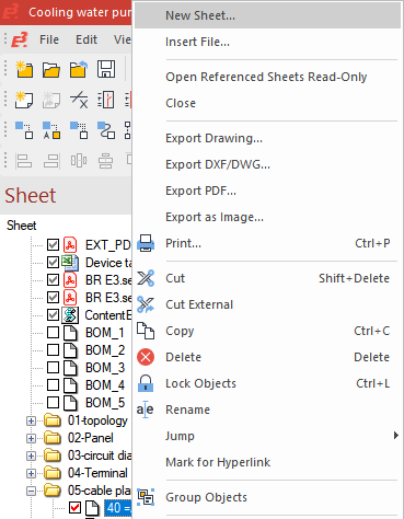
Adding a new sheet
A new window will open in which you can configure the above mentioned options.
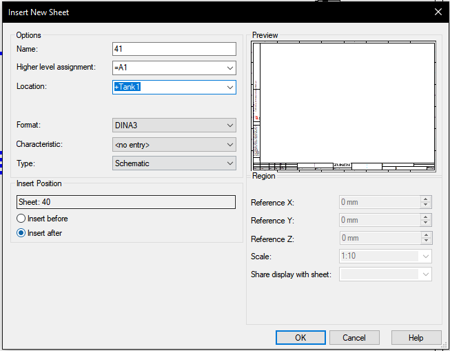
Possible definitions for a new sheet
Then the project's "Devices" window is called up. And the cabling "–W3=A1+Tank1" will be used for the new cable layout shown.
Thus, by right-clicking on the name and "Place New Device View", a new device view is added to the sheet.
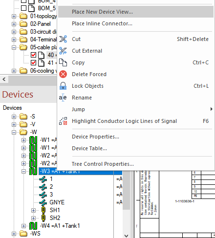
Adding a new device view
This process will be performed three times, each with a different view of the complete documentation.
At first glance, the option "HTS-HE-4-P010SV" and "Place as: complete device" will be used. After adding the device to the sheet, the window for defining the second view is automatically displayed, in which the option "HTS-HE-4-S010SV" is selected. In this addition, the device is rotated with the "Y" key on the keyboard.
This same process is repeated for the "W_ST"/"W_BU" and "TABWIRE3"/"TABWIRE3" views, with the y-axis rotation of the second view.
Watch the Full Video
Subscribe to our Youtube channel here for more technical videos.
Documentation of Segments
Then the connections are added at first glance with the "C" key on the keyboard. Segment size is set to 2mm.
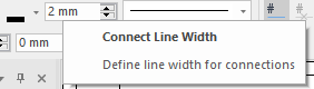
Segment Size Adjustment
In the second view, the "Autoconnect Horizontal" option is used for the automatic connection of segments.
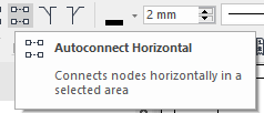
Automatic horizontal connection option
Finally, some descriptions are added at first and second sight.
In the "Misc" table in the project database, the item "CabAndCoreName_hori" is added to the segment of the first view representation.
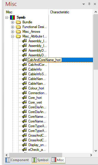
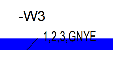
Connections Documentation (Left) and Item Added to Segment (Right) for First View
By double clicking on the option "Insert template Symbol (\)" the specifications were added to the second view of the set of pins.
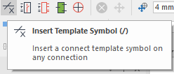
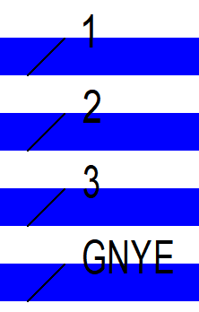
Connections Documentation (Left) and Item Added to Segment (Right) for Second View
Thus, the cable documentation for the project is finalized.
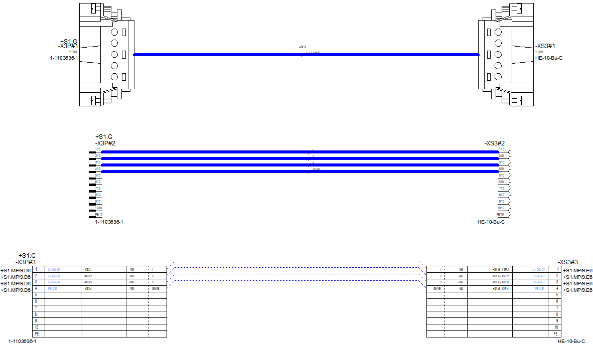
Cable documentation with three different views using E3.cable
Make the E3.series Trial according to your demand using the button below!

Are You a Student?
Download E3.series for free!